


What Is 0-10V Dimming?
The core idea is simple: a low-voltage DC signal — ranging from 0 volts to 10 volts — tells a driver or ballast how bright to be. At 10V, the fixture runs at its maximum output. As the voltage drops toward 0V, the light dims proportionally. The control signal carries information; it does not carry power. The fixture still gets its line-voltage power through a separate switched circuit.
Think of it like the gas pedal in a car. The pedal doesn't make the engine run — fuel and air do that. The pedal just tells the engine how much effort to apply. A 0-10V control wire is the same idea: it's a command signal, not a power source.
This distinction matters more than it might seem. Because the control wires carry only milliamps of current at low voltage, they can run long distances without significant voltage drop issues. They can be wired in parallel across many fixtures on a single zone. And because they're completely separate from the line-voltage circuit, there's no concern about dimming compatibility with inductive or capacitive loads in the same way you'd encounter with phase-cut dimming.
0 Volts Does Not Mean Off
This is the most important technical fact about 0-10V dimming, and it trips up installers and specifiers regularly: a 0V signal does not turn the fixture off. It means minimum dim level — which, depending on the driver, might be somewhere between 1% and 10% of full output. The fixture is still on, still drawing power, just very dim.
To actually switch a 0-10V-dimmed fixture off, you need a discrete switching mechanism on the line-voltage side. That's typically a relay, a contactor, or a switched circuit controlled by a separate output from your lighting control system. The 0-10V signal handles the level; a separate switch handles on and off.
When a 0-10V zone is missing its discrete off capability, you'll see a phenomenon that confuses end users: the lights drop to a very low level but never fully extinguish. The occupancy sensor turns the zone “off,” but there's still a faint glow. Energy compliance auditors notice it immediately. It's a straightforward fix — add the switching output — but it's much easier to address at the design stage than after the ceiling tiles are up.
Sinking vs. Sourcing Drivers
There are two types of 0-10V interfaces: sourcing (also called current source) and sinking (also called current sink). Most modern commercial LED drivers are sinking — they generate their own internal 10V reference and sink current when told to dim. The controller connects across the driver's control terminals and pulls the voltage down toward 0V to dim.
Older fluorescent ballasts were more commonly sourcing, meaning the control wiring worked differently. In practice, the majority of equipment you'll encounter in commercial new construction today is sinking, but it's worth confirming on the driver spec sheet before connecting your control wiring — particularly when retrofitting older systems or mixing product lines.
Mixing a sourcing controller with a sourcing driver (or a sinking controller with a sinking driver) will produce erratic behavior at best and damaged equipment at worst. When in doubt, check the spec sheet first.
One more thing catches people off guard: fixture manufacturers often add capacitive coupling inside the driver to reduce electrical noise. That is normal, but it can leave you measuring a noticeable line voltage between either leg of the 0-10V control pair and ground with a high-impedance meter. That phantom voltage is usually the result of coupling, not usable power — but it is still a reminder to treat 0-10V wiring with caution. It is a control circuit, not something to probe casually or tie into other conductors just because the meter shows an interesting number.
Typical Wiring: The Violet and Gray Wires
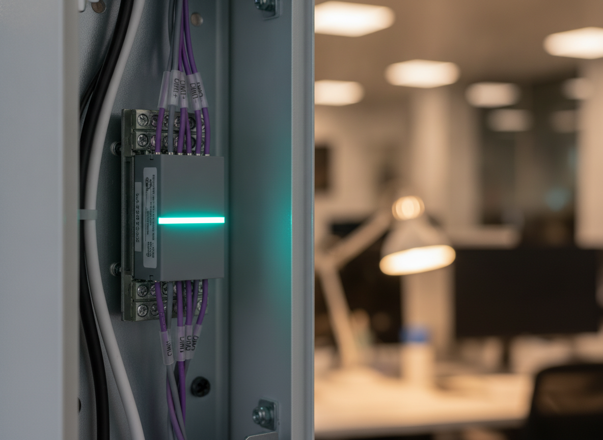
The ANSI/NEMA standard for 0-10V control wiring now uses specific wire colors: violet (+) and pink (−). These are the wires that carry the 0-10V signal between the control device — a wall station, a lighting control panel output, or a sensor — and the driver or ballast. Older field wiring and older literature may still show gray as the negative lead, because the code changed over the past few years.
In a typical 0-10V zone, all drivers in the zone are wired in parallel on the violet and pink conductors. The control device connects once to the zone, and all fixtures respond simultaneously. Because the control signal is low-voltage DC, polarity matters — violet is positive, pink is negative. Reversing them won't always destroy equipment immediately, but it will produce unexpected behavior and should be corrected.
Common Mistakes in 0-10V Installations
- Mixing control wires with line-voltage conductors. The violet and gray control conductors are Class 2 low-voltage wiring. They should not be run in the same conduit as line-voltage wiring, and they should never be connected to a line-voltage terminal by mistake. This is a serious safety hazard and will destroy the driver instantly.
- No discrete off for code compliance. Most energy codes — including ASHRAE 90.1 and IECC — require that occupancy-controlled zones be capable of switching completely off. A 0-10V zone without switching fails this requirement. If you're relying on 0-10V dimming to satisfy occupancy sensor code requirements, make sure your control output includes both a dim signal and a switch.
- Overloading a control output. Each 0-10V output from a control device has a maximum number of drivers it can control before the signal voltage degrades. Check the panel or controller spec for the maximum number of fixtures per zone, especially on large open-office zones with many individual LED drivers.
- Assuming all LED drivers support 0-10V. Some LED drivers only support phase-cut dimming, PWM, or proprietary protocols. A driver that doesn't have a 0-10V input won't respond to a 0-10V signal at all — it will stay at full brightness no matter what the control voltage is.
0-10V in the Context of DALI Systems
DALI (Digital Addressable Lighting Interface) is often described as the more sophisticated successor to 0-10V. That's broadly accurate, but the two protocols coexist in the real world and are sometimes used together. Many DALI systems include 0-10V outputs for compatibility with existing equipment or lower-cost LED drivers that don't support DALI.
The fundamental operational difference is bidirectionality. A 0-10V system is one-way: the controller sends a signal, the driver follows it, and the controller has no way to confirm what the driver actually did. DALI is two-way: the system can query each device, receive status feedback, and detect failures. That feedback loop enables features like emergency lighting testing, energy metering, and fine-grained fault reporting that simply aren't possible with a 0-10V analog signal.
For most standard commercial dimming applications — office lighting, retail, hospitality — 0-10V performs reliably and costs less to implement than DALI. When you need addressability, feedback, or integration with building management systems, DALI is the better choice. Understanding both options and which projects call for which is part of good controls specification. See the comparison table below for a side-by-side view.
Where 0-10V Dimming Excels
For all its limitations, 0-10V remains the most widely supported dimming interface in commercial LED drivers. If you're specifying a project with standard office, retail, or educational spaces and you want broad driver compatibility, straightforward commissioning, and predictable behavior, 0-10V is hard to beat.
It's particularly well-suited to zones where all fixtures in the zone should always behave identically — you dim the zone up and down as a group, and there's no need to address individual fixtures independently. Daylight harvesting zones, general open-office areas, and corridor zones with occupancy-plus-dimming control are all natural fits.
For more context on how different load types interact with dimming systems, and how dimming curves affect perceived light level, those topics are worth reviewing alongside this one.
Protocol Comparison
| Feature | 0-10V | DALI | Phase-Cut |
|---|---|---|---|
| Control type | Analog voltage signal | Digital serial bus | AC waveform shaping |
| Typical wire count | 2 control + switched line-voltage | 2 DALI bus + line-voltage | Line-voltage only |
| Minimum dim level | ~1–10% (driver-dependent) | ~0.1–1% (driver-dependent) | ~5–20% (load-dependent) |
| Needs discrete switch for off | Yes | No (DALI command) | No |
| Bidirectional feedback | No | Yes | No |
| Individual fixture addressing | No (zone-level only) | Yes (up to 64 per bus) | No (circuit-level only) |
| Overall complexity | Low | Medium–High | Low |
Practical Commissioning Tips
- Verify the switched circuit before testing the dim signal. A common commissioning pitfall is testing the 0-10V response before confirming the line-voltage switching is working correctly.
- Test the full range. Walk the dim level from 100% down to minimum and back up. Check for flicker at low end, which can indicate a driver minimum-dim threshold issue or a control signal dropping below the driver's minimum controllable voltage.
- Confirm the 0V floor level. At 0V signal, document what percentage the fixtures actually dim to. That's the system's effective minimum.
- Check for zone bleed. In buildings with multiple adjacent 0-10V zones, verify that dimming one zone doesn't affect an adjacent zone.
- Document the panel wiring. Mark which 0-10V outputs correspond to which zones and which switching outputs serve them.
Need Help Specifying or Commissioning a Dimming System?
Wilco Services commissions lighting control systems nationwide. Whether it's 0-10V, DALI, or a mixed architecture, we make sure it works the way it's supposed to.
Contact Wilco Services